CT power contactors – Revolution in handling DC and AC electric arcs
Single and double pole NO contactors for AC and DC (bidirectional). Rated insulation voltage up to 4,800 volts; conventional thermal current up to 1,100 amps.
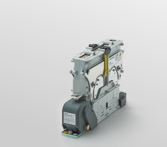
CT1115/04 Single pole NO contactors for AC and DC (bidirectional). Ui = 1,500 V, Ith = 400 A.
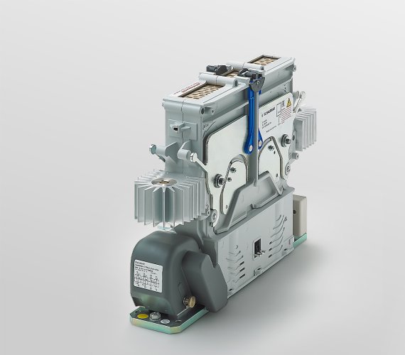
CT1230/11 Single pole make contact contactors for AC and DC (bidirectional). Ui = 3,000 V, Ith = 1,100 A. Heat sink on both main connections.
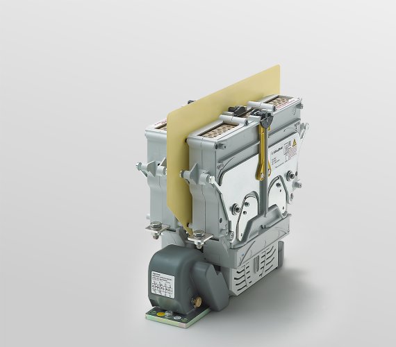
CT1215/04 Double pole NO contactor for AC and DC (bidirectional). Ui = 1,500 V, Ith = 400 A.
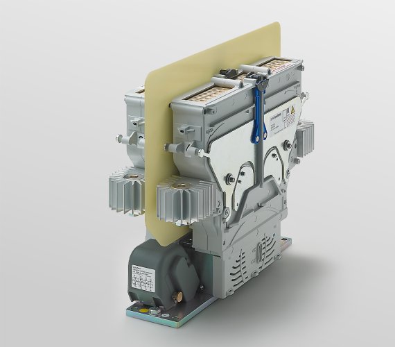
CT1215/04 Double pole NO contactor for AC and DC (bidirectional). Ui = 3,000 V, Ith = 1,100 A. Heat sink on both main connections.
The outstanding feature of the CT range is the unprecedented combination of electromagnetic and permanent-magnetic blowout in one device. In contrast with power contactors with only electromagnetic blowout, the electric arcs are ignited in strong permanent-magnetic blowout fields at the moment of shutdown.
The dwelling times of the electric arcs in the contact zones are thus kept to an absolute minimum. This leads to a significant reduction in shutdown combustion residue. This less wear on the contact surfaces allows for extended maintenance intervals.
The CT concept can be flexibly adjusted to the requirements of customers; e.g. the number of poles, auxiliary contact design or connection technology. The product family of the single and two-pole CT contactors covers a large number of different designs for a wide number of areas of application.
Features
Regardless of the direction of the current
Thanks to the mirror-image design the CT contactor functions regardless of the direction of the current. Unidirectional or bidirectional direct current or alternating current can be switched with the same device.
Low-wear, compact design
The arcs dwell for an extremely short time in the contact zones because they are already ignited in a powerful permanent magnetic field. Burn-up on the contacts is thus kept to a minimum.
The arc itself activates the electromagnetic fields that blow it into the arc chute. Thus the coils only need to feed high current for a minimal amount of time and can therefore be relatively lightly constructed. No additional mechanical or electrical elements are required (advanced contacts, wires, etc.). Thus wear-sensitive components can be omitted and the design remains relatively straightforward and compact.
No critical current range
The CT range also shows its strengths in the reliable shutdown of smaller currents at higher voltages. With smaller currents, the magnetic field of the electromagnets does not suffice. By using permanent magnets, the electric arc is pushed into the electric arc chamber regardless and extinguished. The critical current range typical for purely electromagnetic blowout concepts is not available in the CT.
Power switches in rail and industry
CT contactors are used in various railway networks around the world. However, they are also valued as safety power switches in industry:
- Test benches for high-voltage systems of electric vehicles (main contactor)
- Energy store: disconnection of the intermediate circuit (two-pole CT)
Variants with UL approval
Do you need a CT contactor with UL approval? The variants listed below already have UL approval. In addition, it is generally possible to have every CT contactor UL approved. Please contact us!
| CT1115/10 N 24ECM-00 CT1115/10 N 24ECM-02 CT1115/10 N 110ECM-00 | Single pole CT contactor: Un 1,500 V, Ith 1,000 A Coil voltage: 24 V or 110 V Aux. switch: 00: 2x S870+2x S826, 02: 4x S826 |
| CT1215/10 N 24ECM-00 CT1215/10 N 110ECM-00 | Single pole CT contactor: Un 1,500 V, Ith 1,000 A Coil voltage: 24 V or 110 V Aux. switch: 00: 2x S870+2x S826 |
| CU1215/10 N 48DCM-00 CU1215/10 N 110DCM-00 | Double pole CU contactor: Un 1,500 V, Ith 1,000 A Coil voltage: 48 V or 110 V Aux. switch: 00: 2x S870+2x S826 |
- The UL versions are special versions of the 1,100 A variants without heat sink on the fixed contacts. For this reason, the above-mentioned contactors are approved for a continuous thermal current of 1,000 A max. at an ambient temperature of 70° C max.
- CU contactors are unidirectional variants of the CT series and specially designed for use in PV systems.
Specifications
CT
| Type of voltage | DC (bidirectional), AC (f < 60 Hz) |
| Main contacts, configuration | 1 x SPST-NO or 2 x SPST-NO |
| Nominal voltage Un | 1,500 V or 3,000 V |
| Rated operating voltage Ue | 1,800 V or 3,600 V |
| Rated insulation voltage UNm | 3,000 V or 4,800 V |
| Rated impulse withstand voltage UNi | 15 kV or 30 kV |
| Pollution degreeOvervoltage category | PD3 / OV3 |
| Conv. thermal current Ith | 400A, 800A oder 1,100A |
| Component category | A2 |
| Rated short-time withstand current Icw | series-specific, see catalogue |
| Contact material main contacts | AgSnO2 |
| Aux. contact | 1x S870 (a1), 1x S870 (b0), 2x S826 or 4x S826 |
| Coil voltage Us | 24, 36, 72, 110 V DC |
| Coil tolerance | -30% ... +25% |
| Coil power consumption | series-specific, see catalogue |
| Coil suppression | Suppressor diode / double coil controller (DCC) |
| Mechanical endurance | series-specific: 300.000 min. / 2.000.000 max. operating cycles |
| Vibration / Shock (IEC 61373) | Category 1, class B |
| Mounting orientation | horizontal / vertical |
| IP rating (IEC 60529) | IP00 |
| Temperature range | -40 °C ... +70 °C |
| Storage temperature | -40 °C ... +85 °C |
| Weight | series-specific, see catalogue |
Samples can be ordered here

/en/products/contactors/thank-you/CT – AC and bi-directional DC power contactorContactors