Which Specifications Matter
Five Criteria to Consider When Selecting a DC Contactor

In comparison with semiconductor switches such as IGBTs, electromechanical switchgear has a decisive advantage – galvanic isolation. As the mechanical opening of a DC circuit under load leads inevitably to arcing, which must subsequently be handled and quenched, component selection is, however, not trivial. Associated with this is another difficulty: comparison of the datasheets of the various manufacturers is very difficult. Although EN 60947 does indeed specify classifications for test methods and usage categories, only a very small number of the datasheets contain corresponding information. Moreover, especially for low inductance systems, such as is the case for most battery applications, there is no unifying standard. The following criteria will help you to select the right contactor.
1. The definition of the actual application requirements
The first step for optimum component selection is defining the actual application requirement. In an ideal case, this should take place in the early development phase and in close consultation between the developer and manufacturer of the switchgear. Here, the rated insulation voltage and rated operating current are elementary values. While in most cases it is straightforward to define the voltage, the first problems arise partially in specifying the current. The rated operating current, or, as it is also known, the thermal continuous current, refers to the average current flowing during normal operation. Dependent on the contact resistance of the main contacts in the contactor, which is governed by the contact material and the contact force, the rated operating current causes heating of the contactor. The rated operating current of DC contactors is specified by the manufacturers under clearly defined ambient conditions. Dependent on the actual operating conditions, the actual permissible value can also deviate, without damage being expected. If, for example, the DC contactor is installed in a ventilated control cabinet, overshoots of around 25% are not infrequent. It is important, however, that these must be individually agreed with the manufacturer. The breaking capacity too may partially lie above, but also significantly below the design parameters. Dependent on the application, there are operating points at which short-term current peaks occur. However, for thermal consideration, these can be neglected. Nevertheless, the DC contactor should, in the event of faults, also be able to reliably break the circuit at these operating points.
2. The inductance in the circuit
In addition to the current and voltage values, the inductance in the circuit is also a decisive factor that can significantly influence the breaking capacity. Due to the inductive properties, a voltage peak is generated, dependent on the magnitude of the inductance, which increases the intensity of the arc. For instance the breaking capacity of the Schaltbau DC contactor C294 increases by 300%, if the inductance is reduced from 15 ms to 1 ms.
3. Bidirectional applications
Contactors that aren`t intended for bidirectional applications can only disconnect currents in one current direction. Bi-directional contactors controll both current directions reliably and are therefore ideal for all applications with energy recovery. A typical example of this would be energy storage systems, where batteries are charged and then discharged again. Other application fields for these contactors are: regenerative systems, battery-powered vehicles, DC charging stations.
4. Consideration of the short circuit
As with all applications, monitoring for short circuits must be undertaken. If the DC contactor is appropriately matched to the main fuse, damage to the contactor in the event of a short circuit, should be prevented. For the implementation of safety functions, it must also be determined whether the switch state of the contactor must be monitored. In this case, the contactor needs a feedback circuit.
5. Mechanical and electrical service life
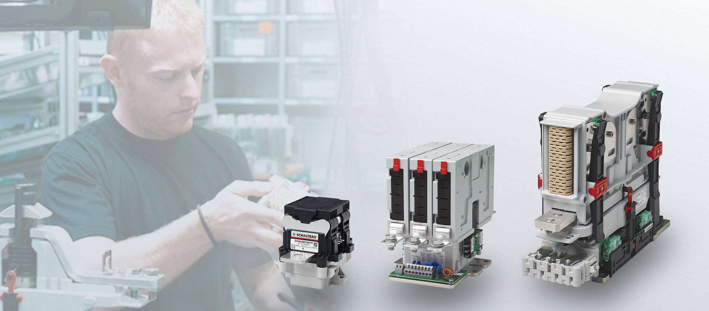
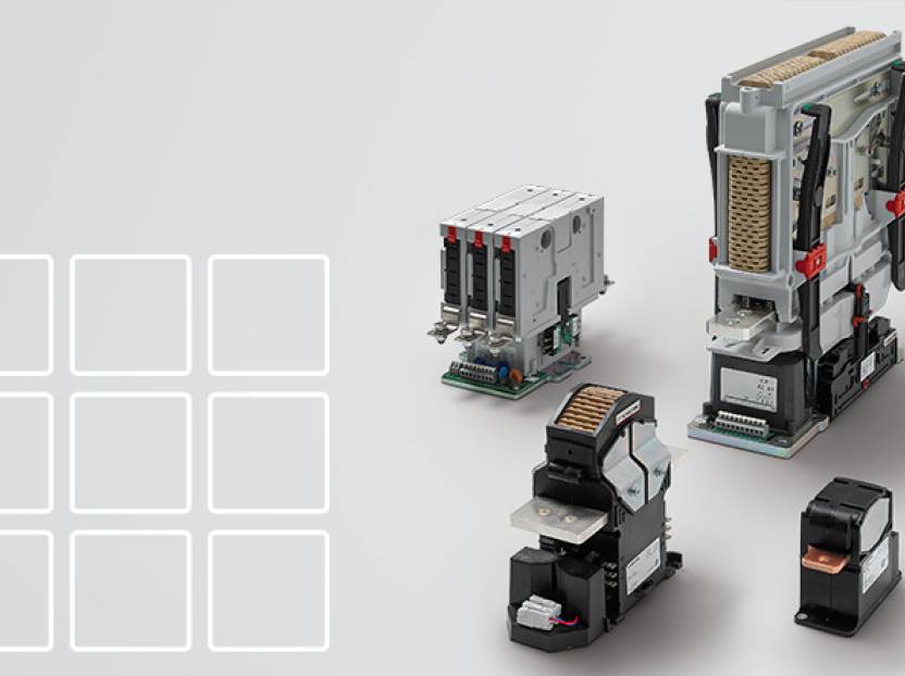
The service life requirement for a DC contactor is essentially defined by the application. Here, a differentiation is made between mechanical (no-load switching cycles) and electrical (switching cycles under a defined load) service life. In many of the latest applications, such as battery storage or also in the automotive sector, the contactor generally switches under no-load. The power electronics regulate the power before the contactor instigates the galvanic isolation. In this case, the requirement relates to the mechanical service life, which is much higher. In this scenario, under-load disconnections are exclusively emergency disconnections, which in general only occur a few times throughout the entire service life of the system. However, there are also a few applications in which the switchgear carries out a hot switching role. In industrial or railway applications, there are cases in which the contactor must disconnect the rated operating current several 100,000 times. Thus Schaltbau GmbH offers, for example, various DC contactors that are designed for such a thermal continuous current. Moreover, the CT series is designed for a high breaking capacity and a high electrical service life with high inductance . By contrast, the C310 series was developed for use in applications in which under-load switching cycles occur only rarely and the inductance is smaller than 0.1ms. This difference is reflected, amongst other things, by the required installation space, weight and cost. Each of these contactor series has been carefully considered in respect of its application, taking into consideration both the technical data and also the costs.


