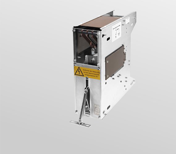
ZH1500 series
Disconnecting and earthing device for single and multi-system rail vehicles
The equipment is designed for all UIC voltages, from 1 kV AC up to 3 kV DC.
The equipment usually is built in behind a door und connected to that door via a rod. Opening of the door pulls the rod and disconnects the connection between the train bus bar and the power supply. The power supply is then connected to ground to allow safe access to the switch gear. This grounded state may be secured with up to 3 locks to prevent a second person to unintentionally connect the power supply again.
The contact system is designed for switching without load but allows some emergency switchings. Under normal operating conditions the main contactor “energy” is being switched off prior to the opening of the contacts via a door switch.
Features
- Disconnecting and earthing device in accordance with the applicable
safety regulations - Suitable for all UIC voltages
- Insulation for operating voltages up to 5 kV DC max.
- Standardised version with the following advantages:
- Can be mounted on the left-hand, right-hand, or bottom side
- Vertically mounted for switchgear cabinets
- Horizontally mounted for power compartments
- Readily available for the project start
Stock items
ZH 1500 D1
ZH 1500 D2
ZH 1500 D2 R
ZH 1500 D2 S
ZH 1500 D2 SK
ZH 1500 D6
ZH 1600 D4
Specifications
| Nominal voltage Unom | Frequency f, | Conv. thermal current Ith |
| Contact | Unom | f | Ith |
| Disconnecting contact | 1.0 kV AC | 16 ⅔ Hz | 150 A |
| 1.5 kV AC | 50 Hz | 100 A | |
| 1.5 kV DC | —- | 100 A | |
| 3 kV DC/Umax. 5 kV | —- | 50 A | |
| Earthing contact | 3 kV DC/Umax. 5 kV | —- | 50 A |
| Auxiliary contacts | 380 V AC | 50 Hz | 16 A |
| 110 V DC | —- | 16 A |
Specifications
| Maximum load | 250 kW |
| Number, configuration | Optional module: 2 x S800 SPDT |
| Blowout method | Arc chute, permanent-magnetic blowout |
| Insulation, testing voltage | 14 kV |
| Cycles, mechanical life | approx. 10,000, 30 years min. |
| Temperature range | -40 °C ... +85 °C |
| Mounting orientation | vertical, horizontal |
| Shock resitance (IEC 61373, IEC 60068) | 3 g, 30 ms |
| Vibration resistance (IEC 61373, IEC 60068) | 0.35 g at 20 ... 150 Hz |
| Ingress protection rating, IEC 60529 | IP00 |
| Dimensions (W x H x T) | 145 x 415 x 470 mm |
| Weight | 11 kg |

